Jan Conradie
PRO Member
Spherical Rhombic Triacontahedron
The rhombic triacontahedron consists of 30 rhombi whose measurements conform to the Phi (Φ) relationship. For instance the length of the long axis of the rhombus must be 1,618 times the length of the short axis. The slope of the rhombus pointing toward the centre of the triacontahedron must be 18° for the 30 rhombi to fit correctly into the structure. These requirements of the rhombic structure must be exact otherwise the 30 pieces comprising the triacontahedron will simply not fit together accurately.
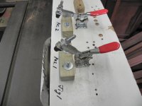
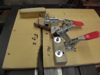
In order to cut the rhombus accurately, wood of a suitable size (we used 95mm x 65mm x 22mm) is clamped in the first position of a jig consisting of a board with a slide attached underneath (i.e. a sled) that fits tightly into the mitre slot of the table saw. The sled has two jigs, or positions, on it. Position 1 is used to make the first cut and position 2 is used to make the second and fourth cut of the rhombus. The third cut is made using an Incra mitre fence explained later. It is critical that the face of the jig in the second position is absolutely parallel to the saw blade. To do this, a dial test indicator attached to a magnetic base was used to determine that the adjustable wooden backstop (Jig 1 Position 2) was exactly parallel to the blade. The blade angle was set 72° relative to the table using a Wixey Angle Gauge. After securely clamping the wood in position 1 with a toggle clamp the first cut was made followed by the second cut using position 2 on the sled.
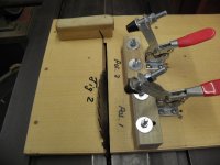
To frame the rhombus with a contrasting color wood, 6 mm thick Imbuia strips were glued totwo pre-cut and opposite sides of the wood described above. These imbuia strips were then trimmed to approx. 2.5mm wide using a second sled (Jig2, Position 1 and 2) which is identical to the first Jig but with positions 1 & 2 set up to achieve the 2.5mm wide imbuia. This yielded a rhombus with two sides covered by Imbuia strips 2.5 mm thick.
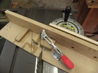
The third cut of the rhombus was done on an Incra 1000HD Mitre fence set to 63.44° relative to the blade or mitre slot. The blade angle remains at 72° (Fig 1). The angle of the third cut is absolutely critical since that determines whether or not the golden ratio (1.618) between the length of the long and short axis of the rhombus is achieved. This cut creates side 3 of the rhombus. The final cut 4 was carried out using position 2 of the second sled (Jig 2b). Using this process, the sides of the rhombus were both parallel and equidistant from one another. It also ensures that all 4 sides were equivalent in length and orientated at the correct angles.
Verification before cutting all the rhombi
In order to verify the angle of the third cut, the short and long axes are carefully measured and checked for the “golden ratio” (long axis 1.618 times the length of the short axis). If the long axis is too short, the angle of the Incra mitre fence must be reduced. If the long axis is too long, increase the angle of the Incra mitre fence slightly. It is also strongly recommended that a second verification be done after cutting 3 rhombi by nesting 3 rhombi together in a circle and checking for any gaps against the light.
Assembly of the Rhombic Triacontahedron
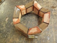
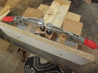
A jig was made to clamp two completed rhombi together at the pre-cut 18° using (Jig 3). Five such ‘double’ rhombi were then clamped together using a hose clamp and glued together with superglue (Fig 2). This circular structure of 10 rhombi comprises 1/3 of the rhombi necessary to complete the structure. From this point onwards, patience and a steady hand is required to glue in, one after the other, the rest of the rhombi (20). Our approach was to first complete one half of the triacontahedron before starting on the second, opposite half.
This is a tedious and tiring aspect of building the triacontahedron, but is the most important part.
Making the Sphere
Early attempts at conventional turning using a chisel invariably resulted in the triacontahedron dislodging from the lathe. This is probably because the grain of the wood changes so rapidly at each joint resulting in a tendency for the chisel to ‘bite’. Eventually an angle grinder fitted with 40 grit sandpaper was used on the knobbly wood and by constant turning of the axis of rotation a rough sphere was eventually obtained. Thereafter, further wood removal was done using sandpaper (80 to 400 grit) on a revolving rubber padded disk inserted in a hand held electric drill. Final finishing was obtained using fine steel wool and then a double coat of sanding sealer was applied before buffing.
The technical and practical contribution of Dereck Nicolson is gratefully acknowledged.
The rhombic triacontahedron consists of 30 rhombi whose measurements conform to the Phi (Φ) relationship. For instance the length of the long axis of the rhombus must be 1,618 times the length of the short axis. The slope of the rhombus pointing toward the centre of the triacontahedron must be 18° for the 30 rhombi to fit correctly into the structure. These requirements of the rhombic structure must be exact otherwise the 30 pieces comprising the triacontahedron will simply not fit together accurately.
In order to cut the rhombus accurately, wood of a suitable size (we used 95mm x 65mm x 22mm) is clamped in the first position of a jig consisting of a board with a slide attached underneath (i.e. a sled) that fits tightly into the mitre slot of the table saw. The sled has two jigs, or positions, on it. Position 1 is used to make the first cut and position 2 is used to make the second and fourth cut of the rhombus. The third cut is made using an Incra mitre fence explained later. It is critical that the face of the jig in the second position is absolutely parallel to the saw blade. To do this, a dial test indicator attached to a magnetic base was used to determine that the adjustable wooden backstop (Jig 1 Position 2) was exactly parallel to the blade. The blade angle was set 72° relative to the table using a Wixey Angle Gauge. After securely clamping the wood in position 1 with a toggle clamp the first cut was made followed by the second cut using position 2 on the sled.
To frame the rhombus with a contrasting color wood, 6 mm thick Imbuia strips were glued totwo pre-cut and opposite sides of the wood described above. These imbuia strips were then trimmed to approx. 2.5mm wide using a second sled (Jig2, Position 1 and 2) which is identical to the first Jig but with positions 1 & 2 set up to achieve the 2.5mm wide imbuia. This yielded a rhombus with two sides covered by Imbuia strips 2.5 mm thick.
The third cut of the rhombus was done on an Incra 1000HD Mitre fence set to 63.44° relative to the blade or mitre slot. The blade angle remains at 72° (Fig 1). The angle of the third cut is absolutely critical since that determines whether or not the golden ratio (1.618) between the length of the long and short axis of the rhombus is achieved. This cut creates side 3 of the rhombus. The final cut 4 was carried out using position 2 of the second sled (Jig 2b). Using this process, the sides of the rhombus were both parallel and equidistant from one another. It also ensures that all 4 sides were equivalent in length and orientated at the correct angles.
Verification before cutting all the rhombi
In order to verify the angle of the third cut, the short and long axes are carefully measured and checked for the “golden ratio” (long axis 1.618 times the length of the short axis). If the long axis is too short, the angle of the Incra mitre fence must be reduced. If the long axis is too long, increase the angle of the Incra mitre fence slightly. It is also strongly recommended that a second verification be done after cutting 3 rhombi by nesting 3 rhombi together in a circle and checking for any gaps against the light.
Assembly of the Rhombic Triacontahedron
A jig was made to clamp two completed rhombi together at the pre-cut 18° using (Jig 3). Five such ‘double’ rhombi were then clamped together using a hose clamp and glued together with superglue (Fig 2). This circular structure of 10 rhombi comprises 1/3 of the rhombi necessary to complete the structure. From this point onwards, patience and a steady hand is required to glue in, one after the other, the rest of the rhombi (20). Our approach was to first complete one half of the triacontahedron before starting on the second, opposite half.
This is a tedious and tiring aspect of building the triacontahedron, but is the most important part.
Making the Sphere
Early attempts at conventional turning using a chisel invariably resulted in the triacontahedron dislodging from the lathe. This is probably because the grain of the wood changes so rapidly at each joint resulting in a tendency for the chisel to ‘bite’. Eventually an angle grinder fitted with 40 grit sandpaper was used on the knobbly wood and by constant turning of the axis of rotation a rough sphere was eventually obtained. Thereafter, further wood removal was done using sandpaper (80 to 400 grit) on a revolving rubber padded disk inserted in a hand held electric drill. Final finishing was obtained using fine steel wool and then a double coat of sanding sealer was applied before buffing.
The technical and practical contribution of Dereck Nicolson is gratefully acknowledged.
Attachments
Last edited: