Follow along with the video below to see how to install our site as a web app on your home screen.
Note: This feature may not be available in some browsers.
Are you looking for a coupon code to buy my software? You can get one from lots of 3rd party sites but they won't work. My software never goes on sale and has never been discounted. The only coupon codes that are given is when I give a club presentation and I offer a discount to the attendees. Other than that, everyone pays the same price.
I have a design where ring 6 & 8 are 12 segments, ring 7 is 6 segments. How can I rotate a ring to achieve a different stagger pattern? When created the joints line up without a stagger.
I got to ask. Did you add or delete rings when building this model?
It is the only way I know that will produce flat rings that are lined up with no stagger.
I played around a bit and it looks like changing the outside diameter will cause the segment alignment to change. I think this means you will need to make the diameters to probably be larger than you want for the finished piece but once the alignment works you should be able to turn it down to size.
Lloyd or one of the other members might have a much better solution.
Give this a try: Double-click on row 5 and then insert a new row and change its board thickness to 0.
This only becomes an issue if you build a vessel with painted segments and then delete a row somewhere below the painted segments. By including a 'null' row to replace that deleted row puts the segments back into their original orientation. You can still get to this row by using the Row selection field to move to the null row where you can delete it or change its properties. Changing the logic and the many places in the user interface that would need to be re-coded to make this not happen would be prohibitively expensive and so it is something you just need to be aware of because if it occurs, there is an easy fix.
Based on the design it looks like every other segment is colored. When the three rings are constructed with the the two rings being 12 segments and the middle being 6 how can you not have a mismatch in alignment? I haven't tried this so I might not be seeing it correctly.
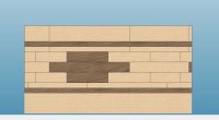
As you can see by the image I posted, the alignment happens correctly when a null row is inserted to replace a deleted row because I built the test rings exactly as mtconsulting built his. Here is an explanation of why this has happened and it all depends on a decision that has to be made at the time you write the software:
The bottom segmented ring has a segment #1. On the next ring, segment #1 has shifted to the right by 50% of the lower segment. But where does segment #1 go on the third ring? If it shifts back to the left so that every odd ring starts at the same place and every every even row starts at the same place. Deleting a row means that every row above the deleted row has changed it's starting position. This wouldn't really be a problem if all the rows had the same number of segments, but the segment below is now twice as wide as the new row and the software did not anticipate this happening at the same place a row was deleted. The software should be able to handle this correctly, but unfortunately, I kept having unintended consequences when I looked at this before. Choosing to shift the position of segment #1 to the right on each successive row solves some of these problems but introduces others.
Changing the software architecture can fix this but since it would have to be done by consultants, it would be very expensive and any new consulting expenditures are now directed to the new software.
I'm going to need to cut and glue up a set of rings because I'm just not seeing how this is going to work in the actual construction when every other segment is light in the both the 6 and 12 segment rings . In your example the 12 segment ring has what appears to be 8 light segments and 4 dark instead of 6 of each. The 6 segment ring has 3 of each.