• Are you looking for a coupon code to buy my software? You can get one from lots of 3rd party sites but they won't work. My software never goes on sale and has never been discounted. The only coupon codes that are given is when I give a club presentation and I offer a discount to the attendees. Other than that, everyone pays the same price.

Wood species does not show up in summary

Thanks for the clarification
I realize everyone seems to think I changed the number of segments but I did not. This is an existing plan and all I did was change height of vessel, height of rows and closed to open.

From my experience the most common problem with the summary table in SP is when the number of segments per row is changed after a design is painted. There may be other things that can trigger the segment tracker database to mess up.

Interesting you say that all you did was change the height. I have not found any of SP profiles to have a base missing like I saw in your plan.
Lloyd pointed out that the last dot towards the bottom of the vessel needs to be closer to the horizontal line. Not sure how that dot got moved up.

For clarification. There a Profiles and there are Plans in SP. Plans are based on a profiles.
- Did you use a profile provided by SP or did you draw the profile?
- If you used a SP profile did you modify/change that profile?
 
It is changing the height of the vessel that is causing this. I checked after every step. I did not change segment count.
I changed from closed to open then checked summary. *This plan is already painted
I changed row height then checked summary
I then changed vessel height and the summary returned to one color.
I am currently starting from scratch so this conversation is just to gather information.

Thank you for your help

Changing height after painting will result in either rows being added when increasing the height or will delete rows if reducing the height.
That can cause the vessel pattern to change.

12 inch heigh bowl.

Screenshot 2024-03-17 080111.png

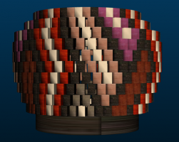
Vessel reduced to 6.5 inches by changing Height. Note the pattern changed.
Screenshot 2024-03-17 080236.png
 
Another thing that would confuse the software (it shouldn’t, of course) is that the bottom dot of your profile is at 0. As stated earlier, that dot needs to be at the radius you want the bottom disk to be so the software would be confused. I never tested for this because, well, I never thought about it.

There are always two easy things to try to recover from an error on the Summary. First, redraw the profile by clicking the ‘Clear’ button which simply lets you switch or redraw the profile. Any painting you have done will still be there after your new profile is created.

Second, go to the Paint screen and click on the Reset All Segments which clears out all of the painted segment data which is corrupt if it doesn’t display correctly. Then repaint how you painted before and the Summary will now be correct.

As I said, the upgrade will fix the repainting problem which occurs when the number of segments per row changes. And now that you mention it, it could also occur if you reduce the height of the vessel. The software has always remembered the segments that were painted and now no longer exist and just a single occurrence of this can cause the Summary to abort before populating the species columns. With the upgrade, if you delete segments either by reducing the segments per row or the height of the vessel, those zombie segments are simply deleted. Problem solved.
 
From my experience the most common problem with the summary table in SP is when the number of segments per row is changed after a design is painted. There may be other things that can trigger the segment tracker database to mess up.

Interesting you say that all you did was change the height. I have not found any of SP profiles to have a base missing like I saw in your plan.
Lloyd pointed out that the last dot towards the bottom of the vessel needs to be closer to the horizontal line. Not sure how that dot got moved up.

For clarification. There a Profiles and there are Plans in SP. Plans are based on a profiles.
- Did you use a profile provided by SP or did you draw the profile?
- If you used a SP profile did you modify/change that profile?
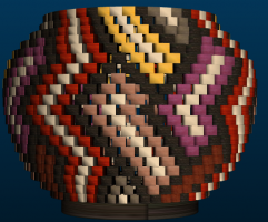
It is a plan designed by someone else using the software and then imported back to my SP.
 
It is a plan designed by someone else using the software and then imported back to my SP.
Thanks for clarifying.
imo, the design pattern is great. The profile has a problem with the bottom node being too high. That produced a no disk bottom.

Should not be that difficult to correct the bottom and repaint the design. Have fun.
Playing with the software is the way I continue to learn.
 
Thanks for clarifying.
imo, the design pattern is great. The profile has a problem with the bottom node being too high. That produced a no disk bottom.

Should not be that difficult to correct the bottom and repaint the design. Have fun.
Playing with the software is the way I continue to learn.
Ok
I started from scratch with the same original plan. I increased the height of the vessel first and then adjusted the bottom dot. I then checked the summary and it stayed intact with the original paint pattern.
I then changed to open segments and changed row height, reset paint and colored as I wanted.
Summary stayed intact!!!

I included the plan as reference

Thanks for your help
 
Last edited:
Thanks for clarifying.
imo, the design pattern is great. The profile has a problem with the bottom node being too high. That produced a no disk bottom.

Should not be that difficult to correct the bottom and repaint the design. Have fun.
Playing with the software is the way I continue to learn.
I do have a couple of questions though:
How do you change the piece count for the accent (solid) rim in SP? I had to add in my exported summary.

Also, does the program adjust the gap degrees based on the design or is it preset to 2 degrees?

Thanks again
 
Last edited:
I do have a couple of questions though:
How do you change the piece count for the accent (solid) rim in SP? I had to add in my exported summary.
Thanks for the new file. Good job. Like it.

Don't think you can. If you want a solid rim the OD and inside Diameter is all you need to make a solid ring for the top.
You could do what you want in WTP. It handles each ring on its own. You cannot import or export a SP file to WTP or WTP to SP.

Also, does the program adjust the gap degrees based on the design or is it preset to 2 degrees?

Thanks again

As far as I know the open segment gap is set in the Bowl Setting (Open Segment Gap). You can change it, but it applies to all open rings.
I played with your new file by changing the Open Gap. It made the changes in the summary. The key is to be in Bowl view, make the gap degree change then go back into the summary to see the results.
 
Last edited:
Thanks for the new file. Good job. Like it.

Don't think you can. If you want a solid rim the OD and inside Diameter is all you need to make a solid ring for the top.
You could do what you want in WTP. It handles each ring on its own. You cannot import or export a SP file to WTP or WTP to SP.


As far as I know the open segment gap is set in the Bowl Setting (Open Segment Gap). You can change it, but it applies to all open rings.
I played with your new file by changing the Open Gap. It made the changes in the summary. The key is to be in Bowl view, make the gap degree change then go back into the summary to see the results.
LOL that is what I did for the rim- used WTP
I think I'll keep the gap as is. More concerned about glue surface.

Thanks again
 
Back
Top