• Are you looking for a coupon code to buy my software? You can get one from lots of 3rd party sites but they won't work. My software never goes on sale and has never been discounted. The only coupon codes that are given is when I give a club presentation and I offer a discount to the attendees. Other than that, everyone pays the same price.

Off Center

TomK

PRO Member
Can someome explaing how they handle centering a segment when they are using a standalone fixture for segment placement. Please refer to the attached picture for claification. If one edge of the segment is on the center line of the bowl the other edge is not pointing to the center. The segments center should be pointing at the center of the bowl but I see no way to accomplish this.
Off Center 2.png
 
I don't set segments this way but if the segment included angle is set correctly (30 degrees for a 12 segment ring, for example) both segment edges and its centerline should point to the same place which is the center of the emerging ring. If they don't, your included angle is wrong.
 
Both edges and the center line all converge at the center of the bowl. Your illustration just shows the segment placed at the wrong distance from the center.
 
Mike is correct. If you move the segment closer to the center, the problem gets worse. If you move it away from the center, where both edges point to the center, that is the correct outside diameter for the SEL of that segment.

Also, the drawing you show has a curve at the diameter of the big circle. Where it crosses the segment, though, is not correct. The outside diameter is measured at the dead center of the outside edge of segment and that single point is the only place that the outside diameter of the ring will be correct and where both edges point to the center.

That means that you can only remove enough wood from the ring until the outside is smooth. You often turn off additional wood, but the calculated diameter is no longer accurate. It isn’t a big difference, but I’m often asked why the actual outside diameter isn’t what was calculated.
 
MikeS is correct. Here is a diagram of a 8: diameter 12 segment ring. Note the two edges of the segment go to the center. If the segment is not at the proper diameter the edges will not point to the center. When the same segment is moved closer to the center the outside edge line does not intersect the true center.

Screenshot 2024-01-06 133724.png
 
Last edited:
Sorry for the late reply. For some reason I could not find my post or the replies until today.

I now understand why both sides of the segment don't align with the center after reading the replies.

To sum it up then, measurements should be made to the ID of the segment and the measurement should be to the center of the segment not the edge. If your measurement is made to the OD and the segment width is over or under the segment sides will not align to the center.

Am I correct with the above statement?
 
The thing to remember is that you are not cutting a ring. You are cutting segments.

Whenever I am ready to make a bowl designed in either Segment PRO or Woodturner PRO, I always export it to a spreadsheet where I can start deleting columns. I always start by deleting the inside and outside diameters. It’s not that they aren’t meaningful - they simply don’t matter. The only things that matter are the Segment Edge Length and board width. The software understands the inside and outside of the wall profile at any elevation. An SEL is calculated that makes a ring that matches the outside wall profile. The board width then makes sure that the ring also matches the inside wall profile. I never measure the diameter because if my SEL and board width are correct, the ring matches the wall profile 100% of the time, whatever it is.

Cut the segments correctly and the bowl will take the shape you designed - inside and out.
 
Last edited:
Whenever I am ready to make a bowl designed in either Segment PRO or Woodturner PRO, I always export it to a spreadsheet where I can start deleting columns. I always start by deleting the inside and outside diameters. It’s not that they aren’t meaningful - they simply don’t matter. The only things that matter are the Segment Edge Length and board width. The software understands the inside and outside of the wall profile at any elevation. An SEL is calculated that makes a ring that matches the outside wall profile. The board width then makes sure that the ring also matches the inside wall profile. I never measure the diameter because if my SEL and board width are correct, the ring matches the wall profile 100% of the time, whatever it is.

The only time you will ever run into problems with a segmented bowl is when the SEL and board width aren’t cut correctly. Focus only on those two things and let the magic begin.
While ignoring the inside and outside diameters may be fine for a glue up that doesn’t depend on them , i.e. using a hose clamp, for the type of jig TomK was asking about the diameter is critical for setting up the jig.
 
That’s true, Mike, but I think Tom was asking a different question..

If I answered the wrong question, it won’t be the first time. ;->
 
Last edited:
Yes, my question is different. First of all I should mention that I'm doing open segments Using a degree platter controlled by a stepper motor (see attached picture). The segment widths calculated in Segment Pro vary the width of the wood for many of the rows. I round up the width calculations in groups so I don't need to cut wood widths for each individual row, many are oversized by 0.100. So, if I were to use the OD for measurement then the segment is out of place and both angles of the segment will not hit dead center. The ID must be used to keep the segment in the correct position. This also keeps the majority of the turning on the outside as opposed to the inside.
 

Attachments

  • Open Segment Fixture.jpg
    Open Segment Fixture.jpg
    68.6 KB · Views: 24
  • Board widths.png
    Board widths.png
    93.1 KB · Views: 22
TomK.
I have not used a fixture like yours or even a manual one like TLohman uses. I have watch some of TLohman videos.

Question I have is If the segment is placed against the fence (angle) and flush against the stop block set at the desired ring diameter(OD) why would the segment not be aligned properly? Should not matter if it is an open or closed segment.

Nice fixture by the way. Would be interested in how you made or purchased the driskell type fixture.
 
Let me start by saying that I do not use indexing wheels with open segments so I do not profess any expertise with this technique.

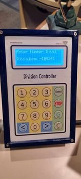
However, If you are using an index wheel with 24 divisions, that would assume that you are using closed segments and the angle for cutting those segments is 7.5 degrees. If you are using open segments using Segment PRO, the segments have been cut at 5.5 degrees. If you are aligning the edge of a 5.5 degree segment with a fence that is expecting 7.5 degrees, the other edge will NOT point to the center.

The gap of a 24 segment open-segment ring is 4 degrees. That means that if you are using an index of 24, you would need to account for the 2 degrees of space that will be on both sides of each 5.5 segment. It is no longer a 24-segment ring. It is 24 segments.

A 24-segment open segment ring is actually 48 segments. 24 segments are wood cut at 5.5 degrees and 24 segments of space that is 1/6” of the width of a 24- segment closed-segment ring.

In other words, you need a SegEasy Plate for 24 segments. This has 24 channels and 24 spacers that add the space for the open space. This means that cutting segments at 5.5 degrees give you segments that slide into the channels with accurate spacing and every edge points to the exact center of the ring.

If you’re not going to use the Stomper (my product), you can get a 24, 36 or 48 segment jig from Jerry Bennett at Title: Seg-Easy Solutions.

You might be able to do this with an indexing solution but you’ll need to go to Tom Lohman’s site to see how to account for the open space. It might be as simple as cutting all the segments at 7.5 degrees.

The other choice is to use closed segments.
 
I use the Stomper (home made version) and Segeasy plates made on my CNC or you can buy from Jerry Bennett. It is by far the simplest approach and there are no alignment issues.
 
I tried building a stomper and did something wrong. The telescoping pole was too flexible to maintain good concentricity.

I too use the Segeasy plate for open segments but I use my 1953 Shopsmith in vertical mode to build my open rings.
My drill press wouldn't work because the table could rotate on the round column when I lowered the table as the piece got taller. The Shopsmith table doesn't move as the spindle moves up but maintains alignment.
 
It’s not a precision instrument but it doesn’t need to be, You need to position yourself above the centered rings and then after applying the glue, you need to rotate the top disk so that four joints in four opposite sides are in alignment. When they are, apply the weight and walk away. The plunger keeps the rings from sliding. As long as you center each centered this way, it will be centered as well as if you had used a precision instrument costing hundreds of dollars more.

This is why I use a wooden stool for the Stomper base. It lets me stand next to it so its able to easily look down at the rings from above.
 
Lloyd,

Lloyd,


Please see the attached picture of what happens to a segment when it is not correctly distanced from the center. Segment "A" is in the correct position with both edges aligned with the center. Segment B is out of position thus throwing off the adjacent side of the segment to center. This only happens when using a rail for the alignment and not a Seg-Easy Plate. If Segment A width is oversized and you measure the OD rather than the ID it will no longer align with the center if the segment width is oversized. This is why it is imperative that I measure using the ID. It took a while for me to get my head rapped around this, but I now know it’s all about where my measurement is made from. Again, this only holds true when using a rail fixture.

I designed and built the open segment jig myself. The Jig is controlled with a Nema 23 stepper motor and stepper motor driver. All power is supplied with an AC to DC converter 24volt DC power supply. The Power supply also provides the power for the controller. The controller was purchased from World of Ward (Title: Store - Rotary Controller). The controller is programmable for the number of divisions or degrees that you desire. It’s capable of degree movements by as little as 0.01 degree. I can program the controller to move by any degree, wait for 15 seconds (segment glue time) sound a beep, them move to the next position in three seconds (the beep tells me to glue is set and its time let go of the segment before the it turns to the next segment) I use Titebond quick and thick for gluing my segments in place. If i prefer to not use the programmable feature of the controller there is an external button that can be pressed to advance to the programmed degrees.

The housing was built with cherry and oak wood and has a powder coated laminated steel surface on wood (glue drops will not stick to a powder coated surface). The segment location rail is supported by two T-Tracks located on the upright and locked in place by tightening the front knob. The two T-Tracks keep the rail perfectly parallel to the platter when moving. The platter was cut from 1/4-inch aluminum plate, painted red and then laser engraved with degree markings. The platter degrees are primally used only as a reference and as my zero indicator. In the center of the platter has a 1" x 8" threaded screw which is the same as my lathe. I'm discovering many othe applications where it comes in handy to have a platter that rotates by degrees. Endless possibilities!
 

Attachments

  • Segment Centers.jpg
    Segment Centers.jpg
    119.6 KB · Views: 15
  • Image 1.jpg
    Image 1.jpg
    13.6 KB · Views: 17
  • Image 2.jpg
    Image 2.jpg
    12.8 KB · Views: 16
  • Image 3.jpg
    Image 3.jpg
    18.1 KB · Views: 15
  • Image 4.jpg
    Image 4.jpg
    14.8 KB · Views: 13
I use the Stomper (home made version) and Segeasy plates made on my CNC or you can buy from Jerry Bennett. It is by far the simplest approach and there are no alignment issues.
Ok, for example if you wanted to change the open gap from 4 degrees to 3 degrees on segment rows. How would you do that?
 
I like your device and would like to build one like it myself. I’ll cite you as the inspiration, of course.

I don’t see any difference between your device and a SegEasy plate. As long as the angle is 5.5 degrees, the SEL will make the segment stop at the diameter calculated by Segment PROand you can use either the inside or outside diameter.

The difference is that without the second ‘fence,’ there isn’t anything to stop the segment at the calculated diameter and so that is what the stop block will do.

All of the trigonometry is simply based on a Unit Circle. Given a particular outside diameter, the formulas calculate the SEL. As you have correctly stated, The place to measure the outside diameter is the center of the outside edge of the segment. When you turn the ring and stop when it is smooth, that should be the calculated diameter. The slightest errors in cutting the SEL will allow this segment to slide closer or stop further from the center of a SegEasy plate so the odds of it matching the calculation that is always correct is pretty small but that’s why segments are made over-sized. The open segment formula is very simple: 360 - (segments * gap_degrees) / segments / 2 so every segment made for a SegEasy plate or your fixture to give a 4 degree gap is 5.5 degrees. Finally, the inside diameter is based on the outside diameter and the width of the board. Because of this, it is more accurate to set the diameter of the outside because using the inside diameter adds one more measurement (board thickness) that will never be perfect. Not only that, but to pick up a lot of speed in the process, you will want to cut as few different board widths as possible and using the inside profile with a board width that is deliberately wrong will guarantee the ring won’t be the desired diameter.If you cut the board width to be wider than calculated, it means that the inside diameter will be smaller and you will have a bit more to remove from the inside of the vessel. Since this takes so little time, it makes sense to have fewer board widths and rounding to a series of rings that can all be made with the same board width.

At the calculated outside diameter a 5.5 degree segment with the calculated SEL will make the segment look like A where both edges of the segment point to the center, just as they would if you were using a SegEasy plate. Advancing the index wheel at 1/24th of a rotation will perfectly space the segments with a 4 degree gap. Changing the formula for any other gap will work exactly the same.
 
The other thing to consider is using Woodturner PRO. Yes, it is slower and both programs use the exact same formulas. There is a difference, though - in Segment PRO, you don’t specify diameters. The software looks at the elevation of the top or bottom of each ring, whichever is larger and then uses some god-awful formulas to see where the profile crosses the Bezier profile at that elevation. This works very well, but there are situations where it might not be what you would do if you were specifying the diameter yourself. In Woodturner PRO, you specify the diameter yourself. Once you’ve done that, the simple trig formula calculates the SEL and finally the inside diameter based on the board width. The outside diameter will always be exactly what you specify.

I don’t think I would find this as a good long-term solution because the minor differences in outside diameters between the two programs should be insignificant and once you get used to working with the calculated diameters of Segment PRO the pickup in speed will be hard to lose.
 
Back
Top