• Are you looking for a coupon code to buy my software? You can get one from lots of 3rd party sites but they won't work. My software never goes on sale and has never been discounted. The only coupon codes that are given is when I give a club presentation and I offer a discount to the attendees. Other than that, everyone pays the same price.

Software question about "width grouping" and width (rip width) error

Shane Howell

PRO Member
Hello-
I just got this software yesterday so I'm a completely new to it. I really like the width grouping option in the summary tab of Seg Pro but notice it groups them be 1/10ths of an inch. Is that locked in or can I changed the setting to something bigger (such as 1/4 inch). Grouping by 1/10th of an inch still leaves a number of different rip widths.
Second question: I previously (prior to using this software) have been extra gracious with my rip widths to allow for some error, maybe 1/8 to 3/16 on both sides of the expected wall thickness in my rip widths. What assumptions does this software give for extra segment width to the desired wall thickness? Do the "Novice", Intermediate" and "Advanced" toggles come into play here, and if so, what are the error associated with each of those?
I guess I have a third question which is in the bottom left corner in the "Cutaway View" can I turn on the desired wall thickness in there to see the desired wall thickness plus the segment blocks to show the error allowed?
Thanks for any help you all can provide.
Cheers,
Shane
 
Hi Shane:
Q1:
- The Optimize Board width when selected round the width to the nearest 1/10th. It cannot be changed within the SP.
A workaround is to export the summary sheet into Excel and make a column with a formula to add what you want.
You do need to keep in mind the outside and inside diameter of the ring to allow enough glue surface between the various rings when turned and shaped on the lathe.

Q2:
- SP has a 1/8th inch blade kerf built into it's calculations.

Q3:
- As far as your third question. SP you can set the wall thickness in the Bowl Setting panel (Wall Width).
The change is reflected in the cutway view.
If you need to know the glue surface between the rings, WoodTurnerPro has that feature.
 
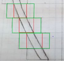
I'm still a little confused. In the vase planning sheet shown, the green boxes represents a plan that has lots of room for error (probably too much error) versus the actual desired wall thickness. Does Seg Pro give something closer to the red box (or red box plus 1/8th on each side), fairly exact dimensions, or something closer to the green boxes and how can I control this? Do I control this by using novice, intermediate, advanced toggles? Or, do I just trick this by saying I want a 5/8" (0.625) thickness but in reality I plan to go to 5/16" or 1/4"?

As for putting into excel to code in the equation, is this something out there on the internet? I'm not sure I would know the right math equations and then excel code/formula to get me there. I do use excel, but this seems like a tough formula to get right.
Thanks, Shane
 

Attachments

  • seg_width_example.JPG
    seg_width_example.JPG
    30.7 KB · Views: 1
I'm still a little confused. In the vase planning sheet shown, the green boxes represents a plan that has lots of room for error (probably too much error) versus the actual desired wall thickness. Does Seg Pro give something closer to the red box (or red box plus 1/8th on each side), fairly exact dimensions, or something closer to the green boxes and how can I control this? Do I control this by using novice, intermediate, advanced toggles? Or, do I just trick this by saying I want a 5/8" (0.625) thickness but in reality I plan to go to 5/16" or 1/4"?

As for putting into excel to code in the equation, is this something out there on the internet? I'm not sure I would know the right math equations and then excel code/formula to get me there. I do use excel, but this seems like a tough formula to get right.
Thanks, Shane

Have you adjusted the wall thickness in the bowl setting box? For example: If you want a wall thickness of 0.25 it can be set in the bowl setting box

it would be helpful if you attached the json file for your project.
Go to Share / Export.
SP will create a json file of your project and put it in the My Segment Pro folder.
You can attach the file to a post.

If you have WTP software that may be more suited for you. It gives complete control of each ring. SP is more "rules" based and in its current form limits somewhat what you can do.

I will respond to your excel question in another post. Working on an example for you.
 
Seems to me you can do what you want by just changing the wall width in the bowl settings. each click of the up/down arrow increases/decreases the wall width by 0.125.

Since you are just wanting to increase or decrease the build wall width before turning. In excel you could just add some number + board width.
for each ring.
 
Thanks. I think I'm going to build something simple and see what dimensions comes out. As you said, Seg Pro is rules based but I don't know what the rules are (error tolerances) that's going on behind the scenes. I'm mid way thru putting something simple together and I'm already noticing this is coming out a bit different than expected.

If you know the excel math to group things together by 1/4" vs 1/10th of an inch, that would be helpful.
Cheers
The "rules" is not about tolerances. It is more about making rings outside the featured ring the same thickness., where spaces are appropriate to use, etc.
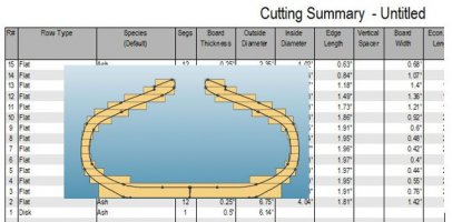
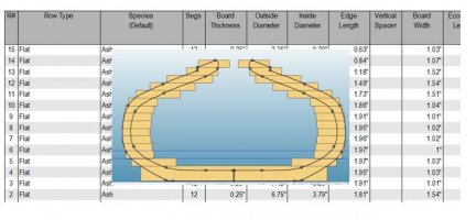
For what you are wanting to do WoodTurnerPro is your best bet at this point. The following images were done in WTP.

In the first image you can see that the board widths vary considerably from ring to ring.
combine 1.jpg

In the second image you can see that I changed the board widths to basically the base, 1" board widths and 1.5 inch board widths. (I did not take the time to change diameters to have eliminate thousands value. By doing so cuts down the stock preperation. It does mean you have more to cut away when turning on the lathe. Just remember the Segment Edge Length is going to determine the diameter of the ring. The board width determines the inside diameter and how much material you have to cut away to get to the final desired wall thickness.
combine 2.jpg
 
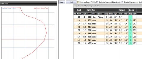
Here is an example from SP in which I Optimized the board width.
Not using Excel it would be easy to use a board width of 1.6" for Row 2,3,7,8
and use a board width of 1.0" for Rows 4,5,6,9
when building the vessel. It just means you are going to cut away more material on the lathe to get to the desired bowl width.
Again. SEL sets Outside diameter of the ring. Board width is for Inside diameter and to ensure enough glue surface between rings.

SP1.jpg
 
Here is how the Wall Width works…

Your outside profile is a single series of Bezier curves and when you select a wall width (.5” for example), the software uses rules (I wrote the rules) to make an inside wall profile that changes as the slope of the profile changes. Where the slope is vertical, the wall width is .5” and you have an overlap of rings that is .5”. As the slope changes, the wall width measurement changes to match the slope. This increases the amount of overlap so that when you turn the vessel by removing the wood that shouldn’t be there, the wall width at any vertical location will be a ‘minimum’ of .5”. Now that the inside wall profile has been created, the two profiles are used to determine the inside and outside diameters of each ring. This is exactly what you would expect it to do.

The reason I say minimum is that the wall width increases as you reach the bottom of the bowl because you must transition the wall profile into the base. You have control as to where this happens. The key is that the second dot from the bottom of your profile instructs the software as to where the wall width transition begins.

Try this test to see how it works. Open any profile and take a look at the Cutaway View. This view shows you exactly what the vessel will look like if you make ALL of the rings EXACTLY as the software specifies and then cut the vessel in half with a band saw. Now grab the second dot from the bottom and move it up or down along the outside profile path and you will see how the board widths at the bottom change the transition to the base.

With regards to skill level, the software doesn’t take that into consideration. In fact, I’m removing the Advance, Intermediate and Beginner functionality because you are the only one that should make decisions about the number of segments you want per row, how thick the rows should be and what wall width you need. At this time, those fields simply take up valuable space and make some elementary changes that only you are capable of making.

In the event that this rules-based approach doesn’t match your needs, switch to Woodturner PRO/3D Design Pro. That solution has no understanding of rules. You are in complete control and you MUST draw both the inside and outside profiles yourself. This means that if you want more wall width in a particular area, just move dots to give you what you want. The trade off is that it will be much slower than Segment PRO.

After you make your first couple bowls, you will know how much wall width you need to allow you to turn the vessel safely and not have to remove more wood than necessary. If you’re just starting out, I suggest a 5/8” wall width is appropriate for a first bowl. Later, you’ll get this down to 3/8” or even 1/4/“ in some circumstances.
 
And a little about board widths…

To reduce the time it takes to build a vessel, you want to reduce the number of board widths where appropriate. Optimizing the board widths is a simple way of doing this, but as you have noticed, it doesn’t give you any granularity other than .10. The control I use only gives me that option and writing my own control is simply not an option.

However, exporting the data to a spreadsheet, as Mike has said, gives you all the control you want and here is what I do. Once I am finished with my design, the last thing I do is export it to a spreadsheet and then I look at the Cutaway View and determine what rows could be made at a particular width. I then copy/paste that value to each of those rows. I then sort the rows so that all the rows with the same width are next to each other and this is the order in which I cut my segments.

The Segment Edge Length determines the outside diameter of the bowl. The inside diameter is calculated based on the board width because it is subtracted from the outside diameter. This means that the wider the board width, the smaller the inside diameter and this means that you will have to remove more wood from those rows when turning. This takes very little time, though, so that is why I minimize the number of board widths so that I can make an entire vessel with as few as four different widths. The shape of your bowl determines if this can be done or not.

Because of this, I can’t write these rules into the software, nor should I. Segment PRO rules determine how to build a vessel from the fields you have modified. How you build that vessel is up to the artist - you. I give you the ability to make simple changes and then get it to a spreadsheet where you can complete the job based on what techniques you want to use.

Lloyd
 
Lloyd: Liked your write up. Says what I was trying to say but more clear.
Thanks for the insight to some of the inner workings (programming) of SP.
 
And a little about blade width…

The only place where the width of the blade has any consequence is the length of the board you need to cut the number of segments from it. I you use a thin blade, my calculation with be slightly more than you need. There is no need to add additional user interface for this setting.

I make this calculation to be exact because you may have a board in your bin that you’d like to use to make a ring. My calculation lets you know if you can get that many segments from it, assuming you make no cutting mistakes.
 
Reading this has made me realize what I need to work with the software - a ruler that measures in 10ths!

I reckon this one ought to work - WeldingStop 6 in Machinist Ruler Scale 5R 10ths 1/100 1/32 1/64 Graduation Flexible Decimal Inch Steel Rule https://a.co/d/3TktM7h
 
I hope this helps- I took the decimal value from the summary and multiplied it by 16 to determine the approximate measurement in inches. For example, .1 is approximately 1/8", .2 is approximately 3/16" and so forth up to .9 and wrote the values on a piece of paper and keep it handy for when I review the summary. These are approximate values. I also did this for .15 through .95 (.5 increments) which give a more accurate value. Probably working with millimeters (mm) would be easier.
 
Back
Top