Glenn McCarron
PRO Member
It's very interesting how different people solve the same issues.
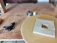
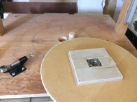
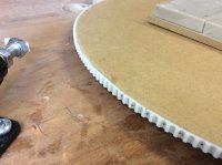
View attachment 2347 I have built an index disc with just an mdf disc and printer indexing cable. You can make index discs for as many positions as you want. The one shown in the picture is for 120 open segments, that is 240 positions using every other position on each row. The diamond vase I posted last week was made with this. The only drawback with this is that discs vary in size for different counts but that is easily accommodated by moving the locking clamp. The cost is only the cost of the printer toothed cable and the mdf or ply. Malcolm.


 Hi Glen. The cable is really a printer drive timing belt as an example from eBay "6mm 2GT White Open Toothed Timing Belt PU Pulley Drive Fr 3D Printer Durable". The disc sits about 15 mm above the base. The base has a dowel glued into it and the dowel is sized to fit snugly into the faceplate that the glue block is fixed to. The faceplate has two spanner flats on it which extend about 12mm from the one end. Beneath the disc is a plate with a square cut out that these two flats fit into so that the faceplate can always be registered in the same place. I mark one of the flats and always use that in the same place. All these pieces are free to rotate about the fixed dowel. There is no bearing or lazysusan used. Hopefully the following pictures will show clearly what the set up is. I will be making a slight modification. I found that when assembling higher pieces there is a little wobble. I intend to support the disc around it's edges to stabilise this, otherwise works ok. (The hole in the baseplate is from an earlier version, and now not relevant). Hope this helps. Malcolm.
Thank you Malcolm for the explanation.View attachment 2348 View attachment 2349 View attachment 2350 Hi Glen. The cable is really a printer drive timing belt as an example from eBay "6mm 2GT White Open Toothed Timing Belt PU Pulley Drive Fr 3D Printer Durable". The disc sits about 15 mm above the base. The base has a dowel glued into it and the dowel is sized to fit snugly into the faceplate that the glue block is fixed to. The faceplate has two spanner flats on it which extend about 12mm from the one end. Beneath the disc is a plate with a square cut out that these two flats fit into so that the faceplate can always be registered in the same place. I mark one of the flats and always use that in the same place. All these pieces are free to rotate about the fixed dowel. There is no bearing or lazysusan used. Hopefully the following pictures will show clearly what the set up is. I will be making a slight modification. I found that when assembling higher pieces there is a little wobble. I intend to support the disc around it's edges to stabilise this, otherwise works ok. (The hole in the baseplate is from an earlier version, and now not relevant). Hope this helps. Malcolm.
Glenn,I wanted to build a Driskell type fixture but I also wanted to upgrade the basic design. My main goal was to keep the cost as low as possible as well.
The heart of the fixture is the index plate at the bottom. I elected to have a 16 inch diameter disc with index holes for 144, 120, 96, 60 & 48. I also had made a reference plate that also had the main index holes as well as a half way hole between each ring of holes. This enhancement will effectively double the capability of the index wheel. It will also provide the offset for every second row of segments.
I approached a fellow Guild member who had done some laser engraving for me on some trophies I had built. I gave him the basic information for my index wheel and he did the rest. And an awesome job he did at a very affordable price. It was made with 1/4 plexiglass.
View attachment 2305 View attachment 2306 View attachment 2307
I also purchased a 1 x 8tpi bolt & nut as well as some T-track with bolts and two knobs. I purchased a 12 inch cast aluminum Lazy Susan.
My first step was to cut a MDF base and a 16 inch circle of MDF for the turntable. I drilled a 1 inch hole in the centre and then mounted it to a disc on my lathe. I had to put it on the outboard side as I can only turn 12 inches over the bed. I turned a dado that would allow the lazy susan to self centre on the bottom. After mounting I drilled a hole that allowed me to rotate the disc to reveal the screw holes to anchor the lazy susan to the base. I had also drilled a 1 3/4 hole in the base so the centre bolt had room to rotate.
I mounted the reference plate today as well.
Next session I will design the post to hold the T-track and anchor and support it.
View attachment 2297 View attachment 2298 View attachment 2299 View attachment 2300 View attachment 2301 View attachment 2302 View attachment 2303
Rick not sure what you are referring to. Can you explain a bit more?Glenn,
Did you create the file that was used for the laser? If so how? Thanks
Rick the file for the laser was created by an acquaintance of mine from our Guild. It was created with Corel Draw.Glenn,
Did you create the file that was used for the laser? If so how? Thanks
Rick I do not have that file. I had explained what I wanted to my Guild buddy and he worked the magic. I did pay him for his services. He may be interested in other work. I could ask? He was very reasonable.Glen,
Any chance you can share the Corel Draw file?
thanks
Glen, I've been following the conversation about the index wheel you had made. I would be very interested in having your friend make one for me. Would you ask if he is interested and if so how much?
Thank you,
Dennis
Rick, I also asked if he would share the file.Glen,
Thanks. I have my own laser & was just hoping to use the file if possible. Rick
Thanks Glen, I sent Trevor an email.Rick, I also asked if he would share the file.
Glen, wondering about the use of the lazy susan. Somewhere, not sure where, the lazy susan had a lot of back and forth play, as in side to side. Is there any play with the one you used to put your index wheel on? You did mention using a cast aluminum lazy susan which may be the answer of not having any play.
Dennis
